Fire Sensor Circuit Circuit Diagram In this video i will shown, how to make fire detector alarm circuit at home, using bc547 and Infrared Receiver.easy to make fire detector alarm at office e

In this project, we will make a simple fire detector alarm circuit using BC547 transistor and IR detector LED on Breadboard. This circuit can easily detect any fire nearby and accordingly start the buzzer. Circuit Diagram of Fire Detector: Component List: 1. BC547 Transistor (NPN) 1no 2. Infrared Receiver LED 1no 3. 220-ohm Resistor 1no 4

Simple Fire Alarm Circuits at Low Cost Circuit Diagram
Here Circuitsgallery comes with a simple and automatic fire alarm and detection system. This fire detection alarm circuit is based on the thermistor. A simple potential divider arrangement using a thermistor is capable of sensing the temperature (presence of fire) and alerting us with a warning signal. This thermistor-based simple fire alarm

Circuit 5 Fire Alarm Circuit Using Germanium Diode. This is a simple fire alarm circuit using Germanium Diode and 555 timer. In this circuit Germanium Diode play very important role in detecting the fire. This circuit is very easy to construct, cost effective and implementable. Block Diagram of Fire Alarm Circuit Using Germanium Diode Fire Alarm circuits are mostly used in industries, homes, cinemas, fuel stations & shopping malls to detect fire accidents. The fire alarm circuit actually gives an alarming signal when the temperature exceeds a certain amount of threshold. Today in this tutorial we are going to make a "Fire Alarm Circuit using 555 Timer". For a better
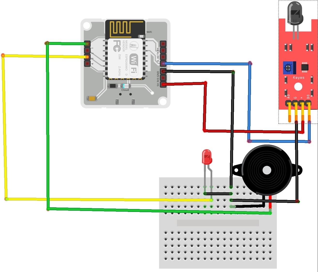
Fire Detector Alarm with BC547 Circuit Diagram
In this video, we will discuss how to make a fire detector alarm at home using BC547 Transistor on Breadboard. During the video, I have shared the circuit di The working and design of a Fire alarm circuit using LM358 is quite simple. LM358 is a dual-operational amplifier. In this project, this IC operates in Comparator mode. The input signals are applied to the inverting terminal whereas non-inverting terminals are compared and the output is produced. Step 5: Power up the Circuit & Adjust the Sensitivity. Working Explanation. The fire Alarm circuit working is simple here we used a 10k NTC Thermistor to detect the fire and an LM358 Operational amplifier in comparator mode. What the thermistor does is when the temperature of the room OR area increases it decreases the resistance and as we look
