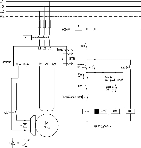
PDF A Methodology for Choosing an Emergency Shutdown System Circuit Diagram 'Emergency off' focuses on the procedure to quickly and safely shut off power to a machine or system in the event of an emergency. 🟧 Emergency 'Stop' 'Emergency stop' focuses on the procedure to quickly and safely shut down a machine or system in the event of an emergency.

The design of the emergency stop, stop category 0, consists of an emergency stop button as an activating switch, a safety relay as a logic unit and a contactor as an actuator for bringing the motor into a non-torque state. See circuit diagram (Figure 2) for connection details. Operation of the safety function When the emergency stop button is Many utilities have diesel generators added to their energy mix to act as an emergency back-up source when a power shutdown occurs. These emergency generators cannot thwart the entire system from going down but are critical for safe shutdown of the plant. Design of Emergency Diesel Generator Control Circuit Logic for Integration with the This circuit is an emergency alert system that uses a NUCLEO-F072RB microcontroller to send SMS alerts and make calls via a SIM800L GSM module, while obtaining location data from a GPS NEO 6M module. The system is powered by a Li-ion battery and includes a TP4056 module for battery charging and protection, with a rocker switch to control power

Emergency Power Off Systems Explained Circuit Diagram
NFPA 75 has two main requirements regarding automatic shutdown — both concerning the release of a clean agent suppression system. The first requirement indicates the need to shut down all electronic equipment in the event of a gaseous suppression system activation. As noted in NFPA 75-2013 8.4.2.1:

section 13.2, Emergency Stop Devices, specifies the following additional switch ("stop control") requirements: • Emergency Stop push buttons shall be located at each operator control station and at other operating stations where emergency shutdown shall be required. • Stop and Emergency Stop push buttons shall be continuously operable from However, instead of automatic transfer switches metal-clad switchgear is used increasing the complexity of the system. Go back to most common arrangements ↑. 3. Hospital arrangements. NFPA 99 and the NEC have very unique requirements for the design of a hospital emergency system. The emergency system is classified into the essential

Design of Emergency Diesel Generator Control Circuit Logic for ... Circuit Diagram
ISA TRANSACTIONS':" ELSEVIER ISA Transactions 34 (1995) 261-272 How to design, verify and validate emergency shutdown systems Dallas L. Green a,*, Arthur M. Dowell, III, P.E. b " Rohm and Haas Company, P.O. Box 584, Bristol, PA 19007, USA b Risk Analysis, Rohm and Haas Texas bzc., P.O. Box 1915, Houston, TX 77536, USA Abstract This paper describes one method to select equipment data and to use
